CAPAS-DR
The Comrod family of CAPAS® Automatic Payload Alignment Systems are designed to meet the challenges faced by public safety, defence and demanding industrial users. CAPAS® systems enables quick and effective deployment of communication or sensor assets in extreme environments without exposing personnel to unnecessary danger.
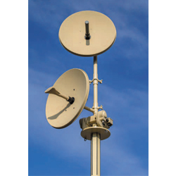
CAPAS-DR Dual Rotator System accomplishes this by allowing independent 360 degree azimuth rotation of two independent payloads. The compact design enables a single mast to be deployed in situations that would previously have required two separate masts.
The powerful drive system coupled with the integrated magnetic compass ensures fast and accurate positioning. CAPAS-DR supports both closed loop and open loop alignment, or a combination of both.
In closed loop alignment mode the system is controlled by a radio transceiver to optimise received signal strength and minimise bit error rate. In open loop mode the system can utilise input from the Comrod TCT Planning System for quick initial positioning. Closed loop feedback from the radio can then further optimise the alignment within a fraction of a degree.
CAPAS-DR is fully rugged per MIL-STD-810, and is suitable for a wide range of deployable masts, including Comrod TM, LMT and ULM series.
REQUEST A QUOTE
| Power Supply | 18 to 52 VDC (MIL-STD 1275E) |
|---|---|
| Alignment Modes | Closed loop mode with transceiver control Open loop mode with magnetic or DGPS compass control Hybrid mode |
| Planning Tool (Optional) | Comrod TCT Mission Planning System |
| Pointing Accuracy/Repeatability | ~ 0.5 degree relative to base |
| Rotating Speed | > 10 degrees per second* |
| Mechanical Limits | Rotation axis: Infinite. Arbitrary limits can be defined in software. |
| Operating Temperature (Ambient) | – 40°C to + 60°C |
| Torque* | > 50 Nm Dynamic, > 250 Nm Static (survival) |
| Payload Capacity* | 2 x 20 kg (maximum in-balance load)* |
| Dimensions (nominal) | Width: 341 mm Height: 772 mm Depth: 278 mm |
| Weight | 15.2 kg |
| Mounting | Lower socket, 50.5 mm Upper payload mounting spigots 50 mm Adaptors are available for a wide range of payloads and masts |
* Dependent on power supply and payload weight/area
| Interfaces | CAN, RS232, RS485, RS42, Ethernet (IEEE 802.3u) |
|---|---|
| Vehicle Power | MIL-STD 1275E |
| EMC/EMI | MIL-STD-461F CE102, RE102, RS103, CS101, CS114, CS115 and CS116 |
| Operating Temperature | Ambient: – 40°C to + 60°C |
| Encapsulation | IP67 |
| Sand and Dust | MIL-STD-810G Method 510.5 Procedure I and II |
| Altitude | Operational – MIL-STD-810G: Method 500.5, Procedure II, 4572 m (15000 ft) at 57.2 kPa Storage – MIL-STD-810G: Method 500.5, Procedure I, 12192 m (40000 ft) at 18.8 kPa |
| High Temperature | Operation: MIL-STD-810G, Method 501.5, Procedure II , 60°C Storage: MIL-STD-810G, Method 501.5, Procedure I, 71°C |
| Low Temperature | Operation: MIL-STD-810G, Method 502.5, Procedure II, – 40°C Storage: MIL-STD-810G, Method 502.5, Procedure I, -51°C |
| Humidity | MIL-STD-810G, Method 507.5, Procedure II, Aggravated |
| Vibration | MIL-STD-810G, Method 514.6C Table 514.6C-VI. Composite wheeled vehicle vibration exposures figure 514.6C-3* MIL-STD-801G, Method 514.6D, Ground Vehicle Category 20, Wheeled/Tracked/Trailer, Procedure I/III* |
| Shock | MIL-STD-810G, Method 516.6, Procedure I, functional Shock, 12 g 11 ms |
* Unit without payload. Permanent mount required for high shock/vibration environments