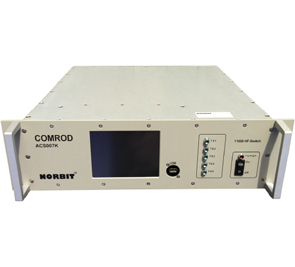
ACS-007K
The antenna switch is intended for use with 5 transceivers together with 1 or 2 antennas. During transmission the active transmitter is automatically connected to the antenna, while an inhibit signal is issued to the other transmitters—the receivers are either disabled, or connected to the (optional) receive antenna.
The receive signal is amplified and distributed to all receivers with a low noise amplifier.
It is possible to give priority to one transmitter. For fail-safe operation one transmitter is connected directly to the antenna in case of power failure.
The unit uses vacuum relays for fast/high power switching. RF sensors are used for TX/RX switching
Ethernet and USB connectors are available for remote control, and interfacing to the radio system. A ¼VGA display is also used for control and indication.
See datasheet for a closer functional description.
REQUEST A QUOTE
| Frequency Range | 1.6-88 MHz |
|---|---|
| Nominal Impedance | 50 Ω |
| TX Signal Path | Power Rating: 500 W continuous, 1000 W PEP Loss: 0.1 dB typical @ <30 MHz 0.2 dB typical @ 30-88 MHz |
| TX/RX Switching | Switching Speed: 1 ms typical Switching Level: 37 dBm ±3 dB SSB Delay: 0..2.55s configurable |
| RX Signal Path | Gain: – 4..2 dB P -1dB, Out: 30 dBm typical IP3, Out: 40 dBm typical Isolation, Out: > 20 dB @ 1.6-30 MHz > 10 dB @ 30-88 MHz Max. inp.Power: 30 dBm continuous |
| Power Supply | 18-32 V @ < 2 A, galvanic isolation |
| Connectors | RF: N female is standard, others on request Power: Amphenol 62GB series, others on request Other: Circular, USB, RJ45 |
| Size | 3U, 19″, 455 mm depth (ex. handles and connectors) |
|---|---|
| Temperature Range | Operational: – 0°C to + 55°C (optional – 20°C to + 70°C) Storage: – 40°C to + 70°C |