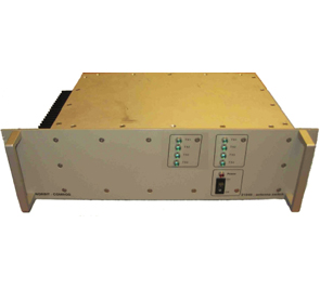
ACS-005K
The antenna coupler is intended for use with 9 transceivers plus 4 additional receivers together with three (4, or 5) antennas. The system has separate paths for VHF (L-VHF + VHF) and UHF. It is possible to transmit or receive on all channels at the same time. The transmit insertion loss depends on the number of active transmitters. Low noise amplifiers are used in the receive paths.
When used with five antennas simultaneous transmission and reception is possible. With only three antennas all reception in that band (VHF or UHF), will be disabled when one or more transmitters are active. It is possible to give priority to one transmitter on each band. L-VHF operation is independent from the other bands. For fail-safe operation one transmitter on each band is connected directly to the antenna in case of power failure. An external switch can be engaged to prevent a specific VHF transmitter from accidental transmission.
See datasheet for a closer functional description.
REQUEST A QUOTE
| Frequency Range | 30-90 MHz, 1 TRX + 5 RX 118-174 MHz, 4 TRX + 2 RX 225-430 MHz, 4 TRX + 2 RX |
|---|---|
| Nominal Impedance | 50 Ω |
| TX Signal Path | Power Rating: 60 W , each transmitter Loss: < 2 dB (one transmitter), or < 8 dB Phase Integrity: < 10° (< 20 mm) Switching Speed: < 100 µs, 20 ms for L-VHF TRX1 Blocking: > 70 dB |
| RX Signal Path | Gain: 0..4 dB P-1dB, Out: > 14 dBm IP3, Out: > 30 dBm Noise Figure: < 4 dB Isolation, Out: > 20 dB Max. inp. Power: 30 dBm continuous Isolation, TX/RX: >45 dB between UHF TX to VHF RX and v.v. |
| Power Supply | 18-32 V @ < 2 A, galvanic isolation |
| Connectors | RF: N female is standard, others on request Power: Amphenol 62 GB series, others on request Blocking Control: BNC female |
| Size | 3U, 19″, 550 mm depth (ex. handles and connectors) |
|---|---|
| Temperature Range | Operational: – 25°C to + 55°C Storage: – 40°C to + 70°C |